
TOTAL SUB
- Jan 28
- 6 min read
Updated: Feb 14
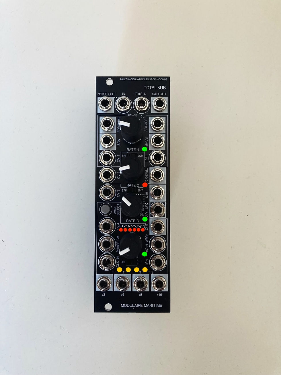
Time to present TOTAL SUB - Multi-modulation source module. Lots of work went on this one to pack a considerable amount of features in the compact 8hp size so very excited about this one!
The aim of this hybrid - analog/digital module is to perform as a true modulation center of the system, capable of complex modulations with possibility of intermodulations between the LFOs and even beyond this - into gate generating tasks! The module features Quad Voltage Controlled LFOs, Dual Random sources of which one fully featured Sample & Hold with Noise source and the second with Stepped and Smoothed output, LFO accepting External Clocks with auto-detection, than a Clock Divider - working with a hidden gate sequencer functioning with external or internal clock, VC clock muliplier and some other advanced features like LFO wave shaping- phase modulation, lfo's curve quantizer, gate ratcheting voltage controlable as well and unipolar or bipolar output. CVs are applicable on external clock also.
So lets start with the top of the module: a classic S&H circuit - Noise as a source of randomness which can be replaced with other signals as the source on the 'IN' input next to it, than Trigg In who is 'normaled' to the neighboring LFO's Square wave but can be replaced with any other gate or trigger source and finally the S&H Out.
LFO 1 disposes all waveforms available simultaneously : Triangle, Saw, Ramp and Square. Has CV over frequency and a Reset input. This LFO has two choices of Range (I or II) - Slow or Fast selectable via the switch above Freq RATE control potentiometer. The range of this LFO is from 0.01Hz to 20Hz.
LFO 2 have a Triangle or Square output (selectable via mini switch above Rate knob), offers CV control over frequency and have an extremely wide range - from very slow to very fast rates. 0.1 to 25Hz
LFO3 provides Triangle Out, CV over frequency and like lfo 2 (both are OTA based), has similar wide range.
LFO 4 provides six waveforms: Square, Saw, Ramp, Triangle, Sine and Random wave mode. Those are selectable via Wave Select button on the left. 6 leds indicating each waveform when selected.
'Random' waveform has a switch allowing to select Stepped or Smoothed version of the random wave.
Internal LFO has a freq. range from 0.1 to 35Hz controlled with Rate potentiometer.
External Clock In: when external clock signal is present it is automatically detected (clock from another LFO, Sequencer, Daw, etc) and will replace the internal LFO - this applies as well on the clock divider. CVs are applicable on the external clock also. When the external clock is disconected the internal will pick up again (after 1s. time-out).
This LFO provides Unipolar or Bipolar output. Unipolar going from 0 to 7V, bipolar -5 to +5V (10V pp)
Offers the following CV controls:
Frequency multiplications CV - following the CV intensity it will multiply the LFO's speed 2x...4x to 8 times actual speed.
Phase CV will introduce the phase modulation creating wave-shaping effect especially when CV source is sine or triangle applied on Sine or Triangle of this LFO (or saw/ramp will work also, square is as usual less affected)
Depth CV is an offset CV creating level-like, amplitude control over LFO's depth.
QNT CV (quantizer) offers 8 quantizations of selected LFO's wave. You can use 0-5V offset to control and tune desired quantization, the 'moving' CV like one of another lfo will walk through those quantizations creating random alterations of the waveform. The following quantifications will be applied:
Chromatic
Major
Minor
Pentatonic Major
Pentatonic Minor
Blues
Dorian
Whole tone
Clock Divider provides 4 divisions of the incoming clock - be it a default internal clock of the LFO 4 or the external. The divisions are : /2, /4, /8, /16 . Clock divider has a Reset input also.
As this LFO is a pretty unique hybrid - integrating analog binary counter into microcontroller's clock logics via internal soft sync of one of divisions - creating temporal feedback loop- this allow the LFO to produce 'strategic gates'. What does it means and how it works?
The gates issued from clock divider provides the information to the microcontroller of exact timing of divisions so the 'smart', less mechanical gates can be placed/generated via LFO's output - to complement the divisions gates with aim to produce more sophisticated rhythms. Varying the speed of the LFO or external clock (giving Tempo) will produce an apparent different Rhythm patterns. Exchanging the place of those generated gates with those coming from clock division (into your drum voices, samplers, etc.) will give different flavors to your rhythms with lots of rhythmic variants. Those gates are available as Gate Patterns when you select 'Random' wave and use QNT CV in. Use 0-5V offset to tune the pattern you want. The gate placement in those patterns corresponds to what would be, in the rhythmical realm, the following placements:
Snare accent
Backbeat
Offbeat
On-beat
Forward
Middle
Reverse
Outside
Syncopated
Shuffle
Alternating
If you use modulating signal (an another LFO for exemple) into this CV (QNT CV) it will walk through those gates patterns creating random gates. Anyway if you look for more randomness of gates there are even more ways to achieve this since the regular purposes of other CVs of this lfo are transformed and adapted for this Gate pattern mode:
CV4 (multiply cv) becomes Ratcheting CV - it will create more or less fast multiplications/bursts of gates on the lfo's output depending on the CV strength/speed (this would be something like "Fill" function on drum machines).
CV Phase on the other hand will rarefy gates (acting like "Break" function on drum machines).
Contradictions between those CVs will create randomness.
(Beside this the most obvious way to achieve more random gates results is to use one of LFOs as a clock and to modulate this LFO by another one or even to modulate the modulating one and so forth)
Depth CV will act on gates also - letting through some gates and 'erasing' some depending on CV behavior.
The patch idea to control gates for one more voice (so 6 voices in total) in synchronised manner is to use one of divisions (via a multiple for ex.) patched into Reset In of the LFO1 on top - and use its Square Out to provide gates to your sixt voice. The lfo's rate will designate the threshold for those additional gates. To resume, you'll have: 4 gates out from Clock divider + 1 aditionnal gate pattern from LFO4 Out + 1 gate from LFO1 square out (via use of reset).
So for exemple you can simply plug your sequencer's clock into the 'clock in' and you're instantly in sync - if you have some drum voices or a sampler you'll easily transform your setup into a groove-box!
Now you'll have an almost hidden compact, intuitive gate sequencer which invites you to think of rhythms in terms of cycles instead of usual dots of the patterns on the screen :)
Hope you'll enjoy using Total Sub!


Size: 8hp, 35mm deep
Power spec. 80mA +12V
50mA -12V
Reverse voltage protected
IMPORTANT Safety notice: The jumper on the rear headers is to prevent from accidentally plugging power cable into those - this would damage the module so take care to keep it in place! The power connector is below with the white stripe indicating red stripe side of your power cable.

Abstract drumming
Making some Cyber-Mediteranean musique 🎶 with Phosgène Wavetable/ FM VCO. The module have two paralel outputs so we hear them both : melody with wavetable and FM bass together. What happens after is that FM goes to différent channel of the VCA and ther’s a magic of TOTAL SUB who, at the same time: sync with the external clock ⏱️, triggers decay’s envelope, modulates CV of the Decay envolope which controls this VCA while modulating the frequency modulation depth on the Phosgene´s CV, than playing gates for drums on the sampler, while providing modulation to ratcheting CV to vary the snare drum's rate and make some gate breaks.. Pretty polivalent! Have some serious doubts that it will be easy to find équivalent :) Always better with headphones 🎧
Another quck patch with clock sync for instant fun :)
Comments